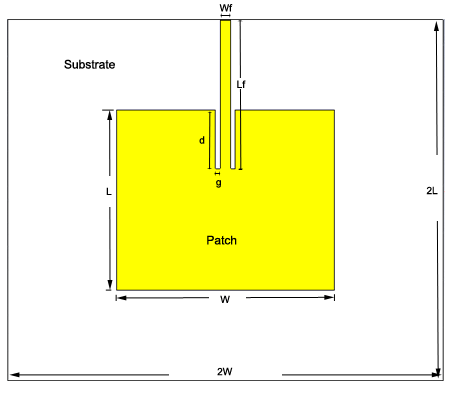


The antenna willbe designed towork in 2.4GHzISM band used inWiFi devices. This is a tutorialseries onmicrostrip patchantenna designwith inset feed inCST microwave. Patch antenna design tutorial withCST microwave Schematics & PCB Tutorials FPGA Tutorials Antenna Tutorials Microcontroller Tutorials Home CST Studio Tutorial Patch antenna design tutorial with CSTmicrowaveīookmark This PageLatest News 6:44 PM How to start mupad, declare function, differentiate, integrate and plot the function? The designed antenna structure is planar, simple and compact since it can be easily embedded for Wi-Fi applications, cellular phones and wireless communications for low manufacturing cost.Patch antenna design tutorial with CST microwave - Electronics Engineering Tutorials Then, the simulation and measurement results were compared. The fabricated antenna was measured by the Vector Network Analyzer. After simulating with the CST software, the patch antenna was fabricated using the MITS milling machine on the FR-4 substrate in the YTU’s communication lab. The designed antenna has the realized gain of 3.42 dB at the resonant frequency of 2.397 GHz.

The proposed antenna is the compact design of 28.2842mm 48.2842mm area on the FR4-epoxy substrate with dielectric constant of 4.4 and thickness of 1.6. The designed microstrip patch antenna consists of a hexagonal patch which is found to be resonant at the frequency of 2.397 GHz with the return loss of -31.2118 dB having satisfactory radiation properties. And the work is the design of a Hexagonal shaped microstrip patch antenna which is presented for the wireless communication applications such as Wi-Fi in S-band. The proposed antenna may find applications in wireless local area network (Wi-Fi) and Bluetooth technology. The proposed MSA is fed by the coaxial probe. The substrate used for the proposed antenna is the flame resistant four (FR-4) with a dielectric constant of 4.4 and a loss tangent of 0.025. The simulation of the proposed antenna was done with the aid of the computer simulation technology (CST) microwave studio student version 2017.

The aim of this work is to design the microstrip patch antenna for Wi-Fi applications which operates at 2.4 GHz. This research covers the study of basics and fundamentals of the microstrip patch antenna. In recent years, the inventions in communication systems require the design of low cost, minimal weight, compact and low profile antennas which are capable of main-taining high performance.


 0 kommentar(er)
